
- Продукция
-
Категории
- Вход/Выход
- Стандартные продукты
- Соединительные платы
- Межплатные разъемы, гибкие печатные платы
- Гибкие печатные платы/шлейфы
- Радиочастотные разъемы
- Волоконно-оптические разъемы
- Модульные/штыревые разъемы
- Межпроводные разъемы
- SD / SIM карты
- Краевые соединители
- Автомобильные разъемы
- Силовые разъемы
- Высокоскоростные разъемы
- Герметичные разъемы
- Инструменты
- Разъемы и датчики
- Coaxial Harness / Adapter Product Search
-
Приложения
- Потребитель
- Cмартфон и Носимый
- Умная техника
- ПК и планшет
- Другое потребительское оборудование
- Автомобильный
- Автономный автомобиль
- Силовой агрегат (для автомобилей)
- Информационно-развлекательная система (для автомобилей)
- Подключенные автомобили
- Автомобильное освещение
- Промышленное оборудование
- Умные сети электроснабжения
- Промышленная автоматизация
- Роботы
- Медицинская
- Телекоммуникации/ Связь
- Информационные центры
- Железнодорожный/ Коммерческий транспорт
- Другое промышленное оборудование
- Автоматизация офиса
- Параметры поиска
- Список избранного * Требуется вход в систему
- Список запросов * Требуется вход в систему


Do you feel the limitations of electrical connection?


1. High Speed Isolation Transmission and Space-saving
Reduce the Number of Isolation Components and Circuit Size

High Speed Isolated Transmission
Photocouplers, isolators and pulse transformers are well known as electrical isolation components. However, one isolation component can only isolate a signal to a transmission speed of several hundred Mbps. On the other hand, the semi-conductor mounted in the BM4MC Series plug enables isolation with photoelectric conversion and high speed isolated transmission from 50Mbps to 6.25Gbps.
Circuit Size Reduction
A single BF4MC Series connector enables high speed isolated transmission at 6.25Gbps, reducing the number of isolation components and allowing for flexible board layout through use of a cable assembly rather than a electrical isolation component, which requires securing of the components across the isolation width.
2. Noise Resistance/ Small Diameter/Bending Resistance
No more shielded cables that are hard, wide, or difficult to bend.

Noise Resistance
Shielding treatment is common for noise resistance however it takes a lot of effort to identify noise sources, frequency, etc. before shield treatment. Since the BF4MC Series uses optical transmission, it is not affected by noise, making EMI prevention easy.
Small Diameter/ Bending Resistance
Cables used in electrical wiring will have a greater diameter and require more shielding in accordance with the transmission conditions (speed, distance, loss, noise). This results in heavier, bulkier cables that are difficult to bend. In contrast, the optical fiber used in the BF4MC Series has much more efficient bending resistance than ordinary fibers. The BF4MC Series maintains a bending radius of R=2.0mm, and a loss of less than 1dB.
Additionally, the BF4MC Series fiber diameter is ø0.5mm regardless of the transmission conditions.
3. Long Distance and Low Attenuation
Low attenuation and accurate long distance
are the biggest advantages of optic communication.

Long Distance and Low Attenuation
Electrical cable attenuation must be considered for long distance electrical transmission. Attenuation varies based on material, cable diameter, etc. When extending a long distance with electricity, a driver or equalize must be inserted in the input/output of in-line device or board’s cable in consideration of signal attenuation. In contrast, attenuation (propagation loss) of the optical fiber used in the BF4MC Series is 5.0dB/km Max. (Wavelength: 850nm)* The BF4MC Series has lower attenuation than electrical cables, enabling long distance transmission without in-line devices or drivers/equalizers.
However, since the optical fiber diameter of ø0.5mm used in BF4MC cannot realistically be routed to outside of devices, a BF4MC cable assembly with LC/SC on one end is available to relay optic fiber cables to the device interface. Please contact Hirose Electric for details on interface connections.
*When fiber length is 1km or longer
4. Low Power Consumption and Simplified Circuit
Low Power Consumption and Simplifed Design
by Reducing the Number of Electrical Components

Low Power Consumption
If there are many transmission conditions, then IC components will need to be added to the electrical wiring depending on the application. The more transmission conditions there are, the number of IC components increases, leading to increased power consumption. The BF4MC Series does not require additional IC components as long as the transmission conditions match the BF4MC specifications, enabling low power consumption.
<BF4MC Power Consumption>
Single power source: 120 mW (Max.)
2 source power: 80 mW (Max.)
Circuit Simplification
A greater number of transmission conditions leads to the electrical wiring requiring additional IC components in accordance with the application. As the number of IC components increases, the circuit becomes more complicated.
If the transmission specifications of the BF4MC Series are met, no additional IC components are required. It works just by usage of the BF4MC recommended circuit and provides circuit simplification. Please refer to the design notes and evaluation boards provides as reference for the recommended circuit. Please contact Hirose Electric for details.
5. Design Support and Product Proposals
Hirose provides support and product proposals
from the early stage of product design.
If you contact us in the early stages of product design,
we will provide you with the most ideal product for the project and support.
Additionally, if you want to switch from an electrical connection to
an optical connection during the design process, please feel free to ask us.
Product Composition, Harness Options
You can choose optical connectors and fiber optic cables according to your application. Please contact us about the application you are considering using optical connectors in and we will be happy to recommend the most suitable combination.
Unidirectional Optical Transmission

When Unidirectional Optical Transmission is Better
Unidirectional Optical Transmission is recommended when either upstream or downstream transmission is high speed and the transmission speed of the other side is slow, as bidirectional optical transmission is not needed. Use of a single-ended optical connector also enables cable routing to the outside of the equipment.
How to Choose an Optical Fiber
Since the BF4MC Series uses a special fiber, the supported cable choices are limited. We recommend single core fiber for intra-board connection and double core cable with a large cable jacket for inter-board/inter-panel connection. (The jacket of single core fiber is 0.5mm in diameter, which is too thin for some applications.)
How to Choose an Optical Connector for Single Side of Harness
Many customers choose LC and SC as general optical connectors. The difference between the two types of optical connector depends on the application, so please contact us and we will do our best to provide the type of optical connector you want to use.

*Change from a fiber diameter of ø0.5mm to a cable diameter that can be routed outside the device with an optical adapter.
Bidirectional Optical Transmission
When Bidirectional Optical Transmission is Better
Choose bidirectional optical transmission when high speed transmission is required for both upstream and downstream, when you want to isolate the signal, or for noise resistance.
How to Choose a Bidirectional Optical Connector
Use the BF4MC Series with two systems and two fibers, or use a single connector with the BF4-IR2 Series.
Optical Transmission Connection Adoption Example and Recommended Applications
[Product Adoption Example]
BF4MC Series in the Power Analyzer (Measuring Instrument)
Company name: HIOKI E.E. CORPORATION
Model name: Power Analyzer (PW6001)
Product Website
In order to send accurate data without destroying the internal computing components (FPGA, CPU and other electronic components), an isolation area must be secured in the measuring device (power analyzer) that measures high power. In normal isolation devices, the voltage that can be isolated is determined by the width of the IC package, but the BF4M Series has been adopted to ensure sufficient isolation voltage (isolation width).

BF4MC is referred to as an optical isolation device in the POWER ANALYZER product catalog.
[Recommended Applications]
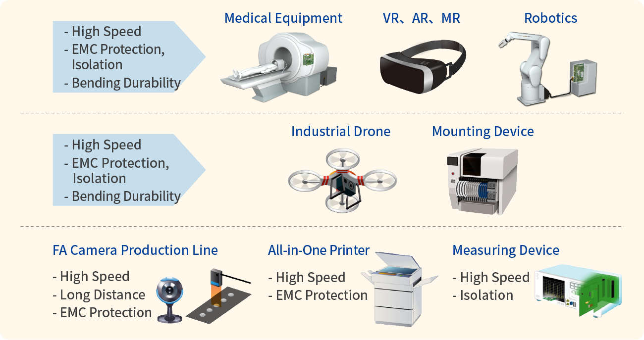
Medical Equipment, Endoscope Video Processors, Endoscopes
Electronic medical equipment used in the operating room must be electrically isolated so as not to affect the human body, are noise resistant so as not to disturb the image due to noise interference from electric scalpels, and support high speed transmission of real-time high-definition video data without delay. We recommend optical connectors to ensure safety.

[Recommended Applications] Industrial Equipment and Industrial Robotics (6-axis Robots, Robot Arms)
The internal connection of industrial robotics needs to be designed with noise prevention, bending resistance and high speed transmission in mind.
| Noise Prevention | Noise from the motors used in each axis can cause disturbances in video and communication, however optical transmission is unaffected by noise. |
| Flexibility | The optical fiber used in the BF4MC Series highly resists bending, and thus supports the flexible movements of industrial robots. |
| High Speed Transmission | Since video signals from the camera mounted on the end of the arm are transmitted to the controller, the cables are mounted near each motor and are easily exposed to noise. Optical connection supports high speed transmission and is an effective method for robot arm connection. |


Due to its Advantages, Usage of BF4MC is Expanding to a Wide Array of Applications


