

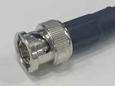
Optimal for 4K (12G-SDI) device connection
By applying design, analysis, and manufacturing technologies such as millimeter-wave connectors, high-speed multi-position connectors, etc., we have greatly revised the BNC75, D.FL75 series design and manufacturing methods for 4K (12 Gbps) equivalent high-speed signals, to achieve 12G-SDI high-speed signals.
Now 4K (12 Gbps) equivalent signals can be transferred
with a single coaxial cable.
Cooperating with chip, board, and cable manufacturers has enabled us to develop a connector that is optimal for 12G-SDI transmission channels. We will provide information on demand required for handling high-speed transmission connectors (10 GHz or more) such as ideal board layout, analysis data, mounting methods, and cable assembly methods.

Features of BNC75 series 12G-SDI compatible Plug
Contact structure provides stable characteristics,
even for high-frequency bands
Design considers higher harmonics to achieve low reflection that is suitable for 12G-SDI transmission. It also inhibits rattling between plug and receptacle after mating, and by changing from conventional surface contact to a multi-point contact structure, high-frequency band fluctuations which often occur at 3 GHz or higher are significantly reduced.
Backlash-eliminating fit
and multi-point contact

Reduce high-frequency
disturbance

Favorable reflectance

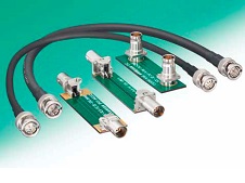
Compatibility with a variety of cables
Each type of cable can be selected depending on use, such as the thick 5.5 C-UHD fastening cable for approx. 80 to 100 m transmission for connection between stations, outside broadcast vans, etc. or the 3.3 C-FW for approx. 30 m transmission, great for optimal resistance to bending in the studio or at the filming location.
Insertion loss by cable

Transmission distance rough standard

Production variations / wiring tools
| Image | Product Name (CL) |
Compatible Cable | Specialized Tool (External Crimping Dies) * |
2D | 3D | RF Report |
s2p | HFSS |
|---|---|---|---|---|---|---|---|---|
 |
BNC(75)-P-5.5C-12G (CL0302-0091-0-00) |
For fixed: 5.5C-UHDG Outer diameter Φ7.7 mm |
Specialized dies: MIL-DTL-M22520/5-55  |
IGES, STEP | - | - | - | |
| For mobility: 5.5C-UHDGW Outer diameter Φ7.7 mm |
||||||||
 |
BNC(75)-P-3.3C-12G (CL0302-0092-0-00) |
For fixed: 3.3C-UHDG Outer diameter Φ5.5 mm |
Specialized dies: MIL-DTL-M22520/5-59 |
IGES, STEP | - | - | - | |
| For movable: 3.3C-UHDW Outer diameter Φ5.5 mm |
The external crimp tool unit: MIL-DTL-M22520/5-01, central crimp terminal unit: MIL-DTL-M22520/7-01), and central crimp terminal positioner: BNC75-12G/CRMD (CL902-3264-0) are common tools. Please note that we do not sell MIL-standard crimp tool units, dies, cable size cutters, terminal processing machines, etc. Please use commercially-available products suitable to your working environment.

For wiring steps, please contact us through “Contact Us” on our website or "Our Sales Representatives." For product specifications, refer to drawing for reference on the product page.
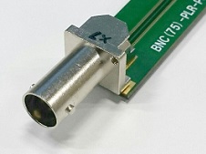
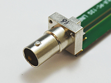
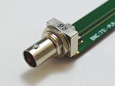
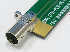
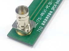
Features of BNC75 Series 12G-SDI-compatible Receptacles
Internal structure, mounting design,
and board pattern were changed to support 12G-SDI
Characteristics enabling 12G-SDI transmission at high frequencies were considered, with a tapered structure used for right angle types, and SMT adopted for center conductor connection (DIP type is also available.) The internal structure was optimized. In addition, to prevent an uneven amount of solder while mounting, nickel barrier processing is used for the right-angle type center conductor.


Compact, lightweight
Usage with an outside broadcast van, etc. was considered to meet a minimal pitch between connectors of 16 mm, and the right angle type's weight was scaled down to 5.3 g. Size will differ depending on the connector, so please check the variation table and 2D, 3D drawings for details.
Product variations
| Image | Product Name (CL) |
Connector Shape |
Center Conductor Mounting Method *1 |
Minimum Mounting pitch (mm) |
Weight (g) | 2D | 3D | RF Report (SI Data) |
HFSS (Web Members Only.) |
PCB Design Guide (Web Members Only.) |
Mounting Guide (Web Members Only.) |
Inventory |
|---|---|---|---|---|---|---|---|---|---|---|---|---|
 |
BNC(75)-PLR-PC-12G-2 (CL0302-0085-0-00) |
Right Angle | SMT | 16 | 9.4 | IGES, STEP | ZIP | ZIP | 〇 | |||
 |
BNC(75)-PLR-PC-12G-1 (CL0302-0083-0-00) |
Right Angle | SMT | 17 | 13.6 | IGES, STEP | 〇 | |||||
 |
BNC(75)-BLR-PC-12G (CL0302-0081-0-00) |
Right Angle | SMT | 17.5 ※2 | 14.6 | IGES, STEP | 〇 | |||||
 |
BNC(75)-PLR-PC(D)-12G-3 (CL0302-0088-0-00) |
Right Angle | DIP | 16 | 5.3 | IGES, STEP | ZIP | ZIP | 〇 | |||
 |
BNC(75)-PR(6)-PC-12G (CL0302-0086-0-00) |
Straight | DIP | 16 | 9.7 | IGES, STEP | ZIP | ZIP | - | 〇 |
* 1. All outer conductor leads are DIP.
* 2. Product compatible with 16.5 mm pitch nut type to be added.
PCB Design guide of test port products available
Our engineering team has developed a detailed guide to assist in your product design. This guide provides essential information to produce the best characteristics when designing test boards. To learn more about this design guide, please contact us.

Features of D.FL75 series
12G-SDI compatible internal RF wiring connection
Improved flexibility of set design by cable connection
Since cable connection can be done with thin-wire coaxial cable from the back of the IF’s BNC, the amount of space available for board positioning, etc. within the casing is improved. This is optimal for broadcasting cameras, etc.

Narrow pitch, multiple level
positioning is possible

Flexible board layout design
is possible

Using a multi-level connection type on the top level allows you to reduce the number of boards. Also, a smaller board-occupied area than with BNC offers board layout flexibility.
Compact, space-saving properties
Receptacle is an SMT (reflow) mount. Because of this, mounting work is significantly reduced compared to flow/manually-attached connectors. A mounting area of 4 mm x 4 mm saves space. When mating the connector, height from the board is 2.7 mm, so the space in height direction is saved as well.

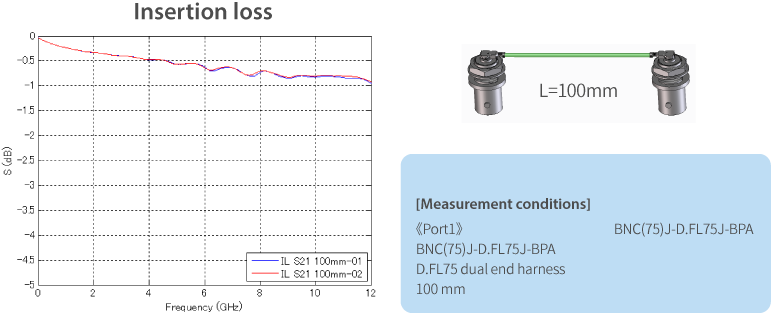
Substantial high-frequency performance for 12G-SDI signal transmission
Return loss is 20 dB (for 12 GHz), which is the same level as with direct board-mounted BNC. Also, routing with coaxial cable in low-loss Teflon dielectric casing can reduce insertion loss more than FR4 board transmission, making it ideal for multiple uses such as connecting smartphone antennas, etc.

Board layout
The layout must be optimized to meet connector and board conditions for 12G-SDI signal transmission. Feel free to contact us about board design reference materials, to check board layouts, etc.
We offer experience in obtaining favorable high-frequency performance, and can support you with board design.
Applications (Usage Examples)


Projectors

