-
Category
-
I/O Connectors
 List of useful search tools
-
Standard Products
List of useful search tools
-
Wire-to-Board
List of useful search tools
- Board-to-Board, Board-to-FPC
-
FPC/FFC Connectors
List of useful search tools
-
RF/Coaxial
List of useful search tools
-
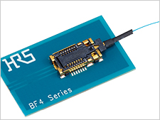
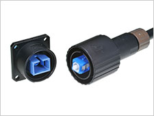
Fiber Optic Connectors
List of useful search tools
-
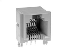
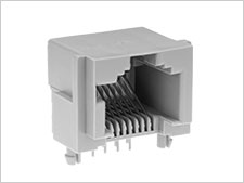
Modular Connectors / Ethernet Connectors
List of useful search tools
-
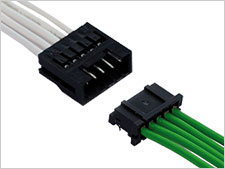
Wire-to-Wire
List of useful search tools
-
IC Card/IC Socket
List of useful search tools
-
Card Edge Connectors
List of useful search tools
-
Automotive Connectors
List of useful search tools
-
Power Connectors
List of useful search tools
-
High Speed Connectors
List of useful search tools
-
Sealed connector
List of useful search tools
-
I/O Connectors
-
Applications
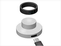
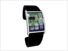
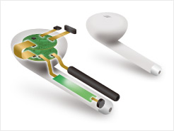
- Smartphone & Wearable
- Smart Appliances
- PC & Tablet
- Other Consumer Equipment
- Autonomous Car
- Powertrain (For Automotive)
- Infotainment (For Automotive)
- Connected Cars
- Automotive Lighting
- Smart Grid
- Industrial Automation
- Robots
- Medical
- Telecommunications/Networking
- Data Centers
- Rail/Commercial Vehicles
- Other Industrial Equipment
- Office Automation
 Recently Reviewed Application
-
Category
-
I/O Connectors
List of useful search tools
-
Standard Products
List of useful search tools
-
Wire-to-Board
List of useful search tools
-
Board-to-Board, Board-to-FPC
-
FPC/FFC Connectors
List of useful search tools
-
RF/Coaxial
List of useful search tools
-
Fiber Optic Connectors
List of useful search tools
-
Modular Connectors / Ethernet Connectors
List of useful search tools
-
Wire-to-Wire
List of useful search tools
-
IC Card/IC Socket
List of useful search tools
-
Card Edge Connectors
List of useful search tools
-
Automotive Connectors
List of useful search tools
-
Power Connectors
List of useful search tools
-
High Speed Connectors
List of useful search tools
-
Sealed connector
List of useful search tools
-
I/O Connectors
-
Applications
- Consumer
-
Smartphone & Wearable
Recently Reviewed Application
Recommended Applications
-
Smart Appliances
Recently Reviewed Application
Recommended Applications
-
PC & Tablet
Recently Reviewed Application
Recommended Applications
-
Other Consumer Equipment
Recently Reviewed Application
Recommended Applications
- Automotive
-
Autonomous Car
Recently Reviewed Application
Recommended Applications
-
Powertrain (For Automotive)
Recently Reviewed Application
Recommended Applications
-
Infotainment (For Automotive)
Recently Reviewed Application
Recommended Applications
-
Connected Cars
Recently Reviewed Application
Recommended Applications
-
Automotive Lighting
Recently Reviewed Application
Recommended Applications
- Industrial Machinery
-
Smart Grid
Recently Reviewed Application
Recommended Applications
-
Industrial Automation
Recently Reviewed Application
Recommended Applications
-
Robots
Recently Reviewed Application
Recommended Applications
-
Medical
Recently Reviewed Application
Recommended Applications
-
Telecommunications/Networking
Recently Reviewed Application
Recommended Applications
-
Data Centers
Recently Reviewed Application
Recommended Applications
-
Rail/Commercial Vehicles
Recently Reviewed Application
Recommended Applications
-
Other Industrial Equipment
Recently Reviewed Application
Recommended Applications
-
Office Automation
Recently Reviewed Application
Recommended Applications


What is a connector? Hirose Electric, a long-established connector manufacturer, answers the simple questions like "What is a connector?” and provides more technical information including important points for mounted products in our Connector Basics You’ll Want to Know Series.
In the second article titled “Key Interconnection Points for Connectors: Cable Connection”, we discuss the first of the three key connection points for proper electrical transmissions, the connection between the cable and the connector.
There are three main types of cable connection methods: solder, which has been around for a long time, crimp, in which the metal terminals are compressed and reshaped, and IDC, in which the cable conductor is pushed into the slit of the terminal. Let's take a look at the differences and features of each.
Cable Connection: Soldering
First, let's talk about connecting cables and connector terminals by soldering. Soldering is an ancient of welded connection in which metals are joined together by melting solder.
Soldering is a simple method of connection cables by joining them to the connector terminals. Since soldering is done manually using a solder iron, connection quality is closely related to the operator’s skill. For this reason, there are soldering skill assessment programs to ensure that soldering is performed properly.

Solder Pot Terminals

Ring Terminal

Cable Connection: Crimping
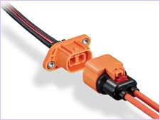
Next, let's talk about crimp termination. This is a wire connection method in which pressure is applied to the terminal and wire, causing the plastic to reshape. The crimped terminal is placed in a housing case and the connector is assembled. An advantage of crimp termination is that it makes quality control easier, as the quality can be determined by the exterior crimp height (C/H: crimp height). Another advantage is that wires of different thicknesses and terminals can be mixed in a single housing.
It is important to note that when the pin count increases, it is easy to misplace the terminals in the housing. In order to prevent this, crimp wiring uses different cable colors and stickers with numbers on them called "mark bands" to ensure that the wires are connected correctly.

Insert the terminal and cable into the crimp tool and compress the handles.

After crimping, put the crimped terminal into the housing to complete the process.
.")
Another advantage of crimped connections is that quality can be controlled based on the crimp height (C/H crimp height).
A variety of tools are available for crimp termination based on the workload.
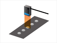
Hand Tools (Manual Crimp Tools)
Hand tools are mainly used during the prototype stage. Connectors and cables are crimped one by one with a special pliers tool.
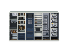
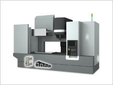
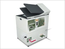
Crimping Machine
A crimping machine is a general purpose tool for crimping with electric or pneumatic pressure.
It is used in conjunction with a dedicated terminal applicator.
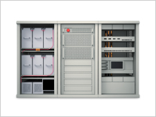
A fully automatic crimping machine measures the length of the wire, strips the cable jacket, and crimps them. It can crimp thousands of wires within an hour.
Applicator
A dedicated crimping unit used with a crimping machine to crimp chain or tape-mounted terminals.
, Fully Automatic Crimping Machine")
Cable Connection: Insulation Displacement Connection (IDC)
Finally, there is insulation displacement connection (IDC). This is a connection method in which pressure is applied to the connector and cable, and the conductor of the insulated cable is pushed into the U-shaped terminal slit to make contact.
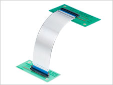
IDC was a widespread connection method due to flat cables (also known as ribbon cables). The wires are aligned parallel to each other on the same flat plane, so that many IDC connections can be made at once with a single press.

Another feature of IDC is that the you can specify the wires used for each connector. The manufacturing cost is reasonable, but the proper wire selection must be made depending on various conditions such as wire type, thickness and the type of connector. When the specified IDC tool is used, the conductor and terminals make contact without any gaps or misalignment as shown below. Please note that processing with a tool other than the specified one may result in a defect.
Compressed Contact (Cross Section)

Contact Between the Core Wire and Terminal
Wire Connection by IDC Hand Press

There are several IDC methods to perform multiple IDC connection on once depending on the equipment and application of the connector, but here we will introduce the method of aligning with a protector and fully automated IDC machines.
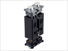
Align the Wires with the Protector and Perform IDC with a Tool
In this method, the wires are aligned through the protector, which is one of the parts of the connector, and then pressurized with a tool to complete the connection.

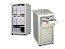
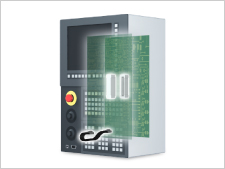
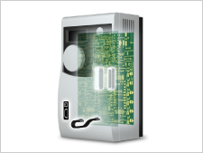
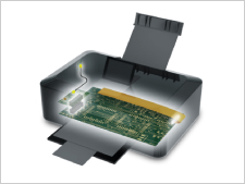
Fully Automated IDC
A connector with crimp terminals on the fully automatic IDC machine is used to measure the cable length, perform the connection and electrical testing.

We have explained the three cable connection methods. In the next article, we will introduce the key points for board mounting.