-
Category
-
I/O Connectors
 List of useful search tools
-
Standard Products
List of useful search tools
-
Wire-to-Board
List of useful search tools
- Board-to-Board, Board-to-FPC
-
FPC/FFC Connectors
List of useful search tools
-
RF/Coaxial
List of useful search tools
-
Fiber Optic Connectors
List of useful search tools
-
Modular Connectors / Ethernet Connectors
List of useful search tools
-
Wire-to-Wire
List of useful search tools
-
IC Card/IC Socket
List of useful search tools
-
Card Edge Connectors
List of useful search tools
-
Automotive Connectors
List of useful search tools
-
Power Connectors
List of useful search tools
-
High Speed Connectors
List of useful search tools
-
Sealed connector
List of useful search tools
-
I/O Connectors
-
Applications
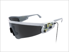
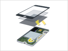
- Smartphone & Wearable
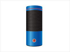
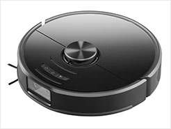
- Smart Appliances
- PC & Tablet
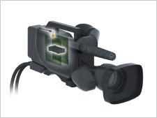
- Other Consumer Equipment
- Autonomous Car
- Powertrain (For Automotive)
- Infotainment (For Automotive)
- Connected Cars
- Automotive Lighting
- Smart Grid
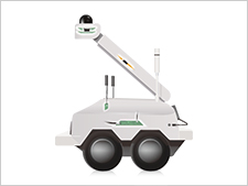
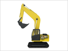
- Industrial Automation
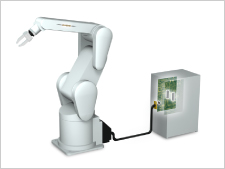
- Robots
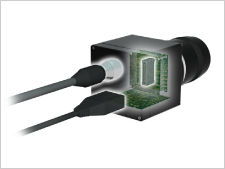
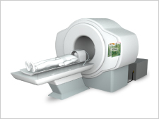
- Medical
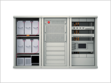
- Telecommunications/Networking
- Data Centers
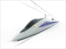
- Rail/Commercial Vehicles
- Other Industrial Equipment
- Office Automation
 Recently Reviewed Application
- -
-
Category
-
I/O Connectors
List of useful search tools
-
Standard Products
List of useful search tools
-
Wire-to-Board
List of useful search tools
-
Board-to-Board, Board-to-FPC
-
FPC/FFC Connectors
List of useful search tools
-
RF/Coaxial
List of useful search tools
-
Fiber Optic Connectors
List of useful search tools
-
Modular Connectors / Ethernet Connectors
List of useful search tools
-
Wire-to-Wire
List of useful search tools
-
IC Card/IC Socket
List of useful search tools
-
Card Edge Connectors
List of useful search tools
-
Automotive Connectors
List of useful search tools
-
Power Connectors
List of useful search tools
-
High Speed Connectors
List of useful search tools
-
Sealed connector
List of useful search tools
-
I/O Connectors
-
Applications
- Consumer
-
Smartphone & Wearable
Recently Reviewed Application
Recommended Applications
-
Smart Appliances
Recently Reviewed Application
Recommended Applications
-
PC & Tablet
Recently Reviewed Application
Recommended Applications
-
Other Consumer Equipment
Recently Reviewed Application
Recommended Applications
- Automotive
-
Autonomous Car
Recently Reviewed Application
Recommended Applications
-
Powertrain (For Automotive)
Recently Reviewed Application
Recommended Applications
-
Infotainment (For Automotive)
Recently Reviewed Application
Recommended Applications
-
Connected Cars
Recently Reviewed Application
Recommended Applications
-
Automotive Lighting
Recently Reviewed Application
Recommended Applications
- Industrial Machinery
-
Smart Grid
Recently Reviewed Application
Recommended Applications
-
Industrial Automation
Recently Reviewed Application
Recommended Applications
-
Robots
Recently Reviewed Application
Recommended Applications
-
Medical
Recently Reviewed Application
Recommended Applications
-
Telecommunications/Networking
Recently Reviewed Application
Recommended Applications
-
Data Centers
Recently Reviewed Application
Recommended Applications
-
Rail/Commercial Vehicles
Recently Reviewed Application
Recommended Applications
-
Other Industrial Equipment
Recently Reviewed Application
Recommended Applications
-
Office Automation
Recently Reviewed Application
Recommended Applications


What is a connector? Hirose Electric, a long-established connector manufacturer, answers the simple questions like "What is a connector?” and provides more technical information including important points for mounted products in our Connector Basics You’ll Want to Know Series.
In this article, we will be discussing the third and final connection key point for the correct transmission of electricity: the contact area. During the final assembly, the connectors are fitted together in a process called "Mating”. This article explains what points are involved in the mating process to ensure that electricity is transmitted correctly and stably.
The Contact Resistance Value Matters

Connector mating, the process of fitting two connectors with complementing shapes together, is a task that requires specialized skills and knowledge. In many cases, assembly is done not by the connector, cable, or board mounting manufacturers, but by a specialized assembly manufacturer or a dedicated connector mating department when handled internally.
While the role of the contact area is very important when mating connectors, the quality of the contact area is determined based on the stability of the resistance value at the contact area of the conductors. The resistance value of the contact is always listed as "contact resistance" in connector catalogs and specification sheets.
Stabilizing the Contact Resistance Value
If the contact resistance is unstable, electricity cannot be transmitted correctly. For this reason, connector manufacturers have incorporated various design innovations in their connectors in order to stabilize contact resistance.
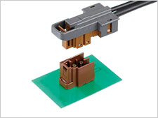
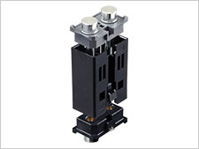
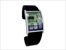
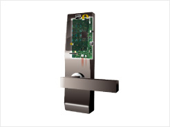
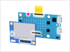
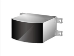
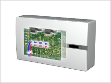
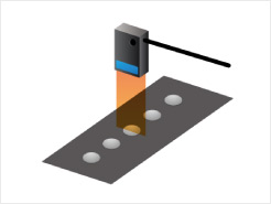
[Preventing Film Resistance]
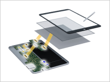
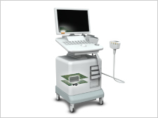
Increase Contact Pressure
![[被膜対策] 接触圧力を高める](https://prd-4s-public.s3.ap-northeast-1.amazonaws.com/sys-master/public/h6b/h31/9107414646814/Content_4_3.png "[被膜対策] 接触圧力を高める")
Terminal contact areas come in a variety of shapes and sizes, but they are all made of metal, so an oxide film can form on the surface. Increasing the contact force enables the terminal contact area to break through the oxide film and transmit electricity correctly.
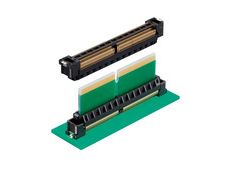
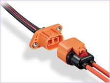
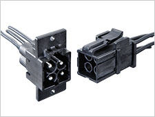
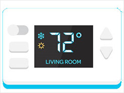
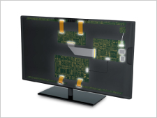
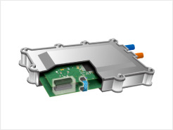
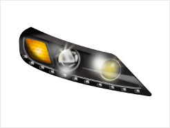
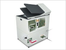
[Corrosion Prevention]
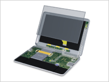
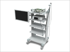
Plating on the Contact Portion
![[腐食対策] 接点部にめっきを付ける](https://prd-4s-public.s3.ap-northeast-1.amazonaws.com/sys-master/public/h3a/h3b/9107414908958/Content_4_4.png "[腐食対策] 接点部にめっきを付ける")
The metal surface of the terminal will oxidize and corrode, becoming non-conductive overtime. To prevent this, suitable plating is applied to the terminal contact area and the solder area to mitigate loss of conductivity and maintain stable contact resistance over a long period of time.
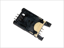
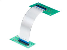
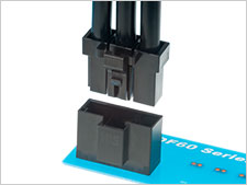
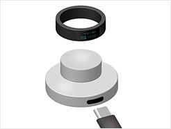
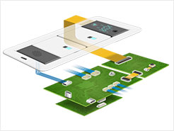
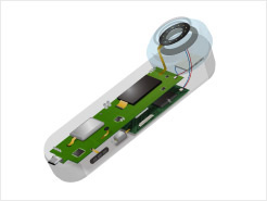
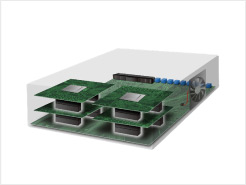
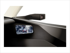
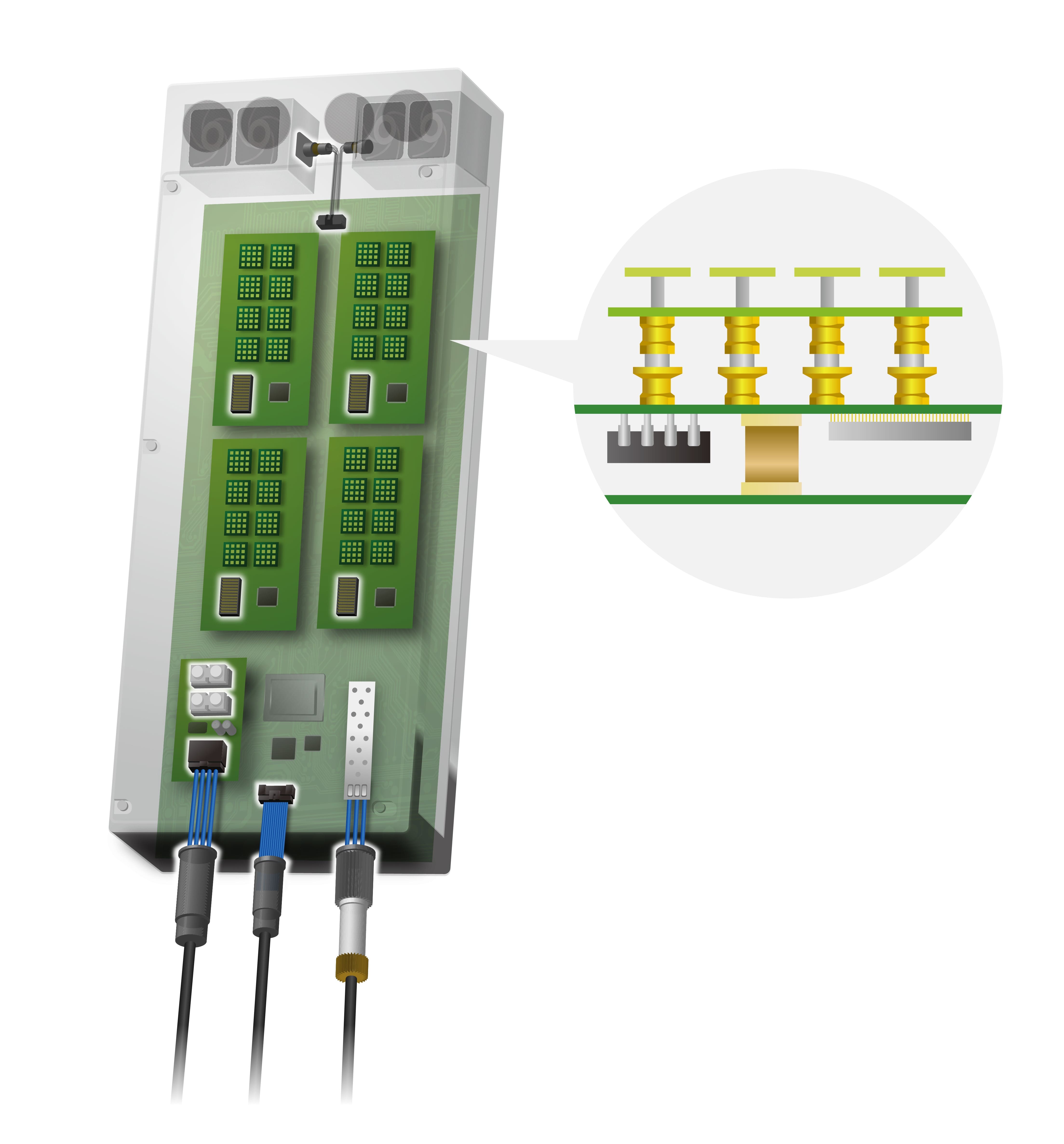
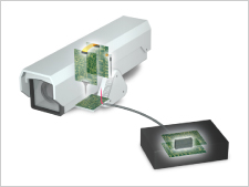
[Vibration Countermeasure]
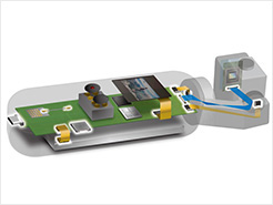
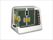
Securing the Contact Point
![[Vibration Countermeasure] Securing the Contact Point](https://prd-4s-public.s3.ap-northeast-1.amazonaws.com/sys-master/public/h0f/h29/9121420148766/EN_Content_4_5.png "[Vibration Countermeasure] Securing the Contact Point")
Various types of equipment, including automotive and industrial equipment, generate vibration. Vibration wears down the terminal contact area and causes connector malfunction. However, the impact of the vibration can be reduced by securing the connector contact points.
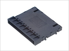
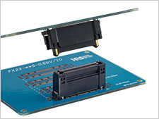
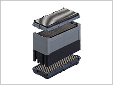
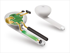
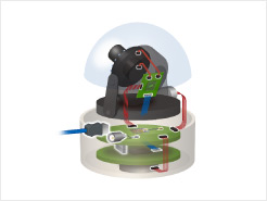
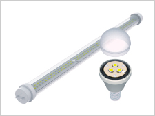
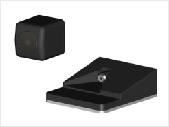
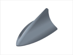
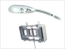
[Dust and Dirt Adhesion Prevention]
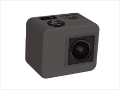
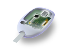
Multi-point Contacts
![[Dust and Dirt Adhesion Prevention] Multi-point Contacts](https://prd-4s-public.s3.ap-northeast-1.amazonaws.com/sys-master/public/hf0/h32/9121420410910/EN_Content_4_6.png "[Dust and Dirt Adhesion Prevention] Multi-point Contacts")
Some devices are used in environments with dust and dirt. Connectors with a multi-point contact design can be adopted for devices with such usage environments in order to maintain the contact resistance even when contamination to the connector occurs.
How to Select The Type of Plating Applied to The Terminals
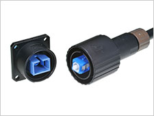
Plating is applied to the contact area in order to stabilize contact resistance, but we often receive questions on how to select the plating material. When in doubt, please select the plating based on the operating environment of the equipment and the circuit current. If you use gold plating for all of your products, the contact resistance will be stable. However you can reduce costs by selecting tin plating instead of gold when appropriate.
Refer to the following operating conditions as a guide when selecting between tin and gold plating.
| Plating Specifications | Tin Plating | Gold Plating |
|---|---|---|
| Mating Durability (Cycles) *1 | Less than 30 times | Less than 50 times |
| Vibration *2 | None | Present |
| Environmental Stress *3 | None | Present |
| Current Used | 100μA or more | 100μA or less |
*1: The mating durability differs depending on the Hirose product series. For details, please refer to the series catalog.
*2: Constant or intermittent exposure to vibration and shock.
*3: Examples of environmental stress: Hydrogen chloride, salt water, sulfur participation, outdoor environment, continuous high-load cycling, etc.
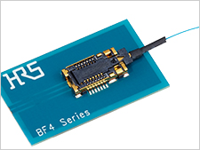
In the next article, we will explain connectors based on the following components: shielded cable, FPC/FFC, coaxial cable, and optical fiber.