-
Category
-
I/O Connectors
 List of useful search tools
-
Standard Products
List of useful search tools
-
Wire-to-Board
List of useful search tools
- Board-to-Board, Board-to-FPC
-
FPC/FFC Connectors
List of useful search tools
-
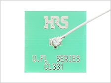
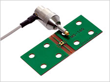
RF/Coaxial
List of useful search tools
-
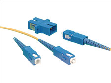
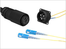
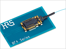
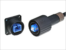
Fiber Optic Connectors
List of useful search tools
-
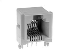
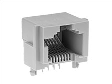
Modular Connectors / Ethernet Connectors
List of useful search tools
-
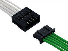
Wire-to-Wire
List of useful search tools
-
IC Card/IC Socket
List of useful search tools
-
Card Edge Connectors
List of useful search tools
-
Automotive Connectors
List of useful search tools
-
Power Connectors
List of useful search tools
-
High Speed Connectors
List of useful search tools
-
Sealed connector
List of useful search tools
-
I/O Connectors
-
Applications
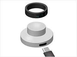
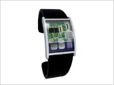
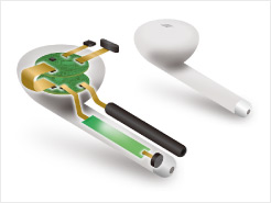
- Smartphone & Wearable
- Smart Appliances
- PC & Tablet
- Other Consumer Equipment
- Autonomous Car
- Powertrain (For Automotive)
- Infotainment (For Automotive)
- Connected Cars
- Automotive Lighting
- Smart Grid
- Industrial Automation
- Robots
- Medical
- Telecommunications/Networking
- Data Centers
- Rail/Commercial Vehicles
- Other Industrial Equipment
- Office Automation
 Recently Reviewed Application
- -
-
Category
-
I/O Connectors
List of useful search tools
-
Standard Products
List of useful search tools
-
Wire-to-Board
List of useful search tools
-
Board-to-Board, Board-to-FPC
-
FPC/FFC Connectors
List of useful search tools
-
RF/Coaxial
List of useful search tools
-
Fiber Optic Connectors
List of useful search tools
-
Modular Connectors / Ethernet Connectors
List of useful search tools
-
Wire-to-Wire
List of useful search tools
-
IC Card/IC Socket
List of useful search tools
-
Card Edge Connectors
List of useful search tools
-
Automotive Connectors
List of useful search tools
-
Power Connectors
List of useful search tools
-
High Speed Connectors
List of useful search tools
-
Sealed connector
List of useful search tools
-
I/O Connectors
-
Applications
- Consumer
-
Smartphone & Wearable
Recently Reviewed Application
Recommended Applications
-
Smart Appliances
Recently Reviewed Application
Recommended Applications
-
PC & Tablet
Recently Reviewed Application
Recommended Applications
-
Other Consumer Equipment
Recently Reviewed Application
Recommended Applications
- Automotive
-
Autonomous Car
Recently Reviewed Application
Recommended Applications
-
Powertrain (For Automotive)
Recently Reviewed Application
Recommended Applications
-
Infotainment (For Automotive)
Recently Reviewed Application
Recommended Applications
-
Connected Cars
Recently Reviewed Application
Recommended Applications
-
Automotive Lighting
Recently Reviewed Application
Recommended Applications
- Industrial Machinery
-
Smart Grid
Recently Reviewed Application
Recommended Applications
-
Industrial Automation
Recently Reviewed Application
Recommended Applications
-
Robots
Recently Reviewed Application
Recommended Applications
-
Medical
Recently Reviewed Application
Recommended Applications
-
Telecommunications/Networking
Recently Reviewed Application
Recommended Applications
-
Data Centers
Recently Reviewed Application
Recommended Applications
-
Rail/Commercial Vehicles
Recently Reviewed Application
Recommended Applications
-
Other Industrial Equipment
Recently Reviewed Application
Recommended Applications
-
Office Automation
Recently Reviewed Application
Recommended Applications


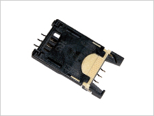

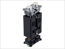
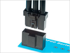


QR/P18 Series Scheduled to be discontinued
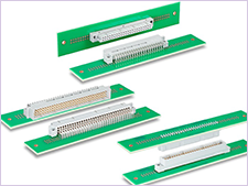
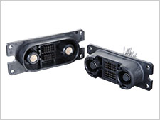
High-Pin-Count Rectangular Rack/Panel ID Connectors

Features
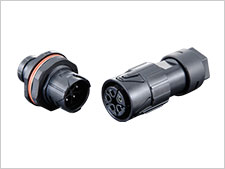
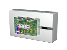
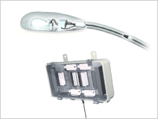
Rectangular, High-Pin-Count Rack/Panel Insulation Displacement Connectors (IDC)
The QR/P18 Series of miniature rack/panel connectors is designed for the complete segmentation of the structure of the external holder/terminal units of the well-received QR/P Series of plug-in rectangular rack/ panel connectors; furthermore, the subsequent insertion of the harnessed terminal unit affords a more efficient harness mounting task. These connectors are configured with 12, 18, or 24 pos.(IDC) in the signal line, and 4 pos.(crimp) in the power line.
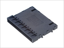
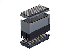
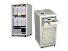
1. Completely separated structure of the external holder/terminal unit
In order to improve the harness procedures, the connectors are designed for the complete segmentation of the external holder and the signal/ power supply unit, and inserting the harnessed contacts aims to improve the workability of the power supply/signal line harness as well as the mounting to the set.
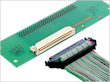
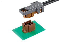
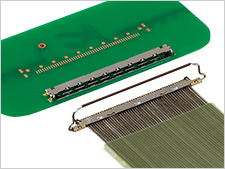
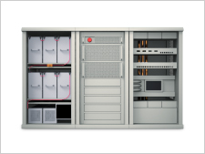
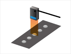
2. Signal unit
The signal unit uses the highly reliable insulation displacement connection method. (The wire is AWG #26 and the insulation outter diameter is 0.88mm.) The insulation displacement procedure can now be used by attaching a special applicator to a commercially available automatic insulation displacement machine, or a manual press tool can also be selected.
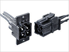
3. Power supply
The power supply terminals permit the use of a crimp harness using wire of AWG#16 to 18 (and insulation outside diameter of 2.1 to 2.2mm), and can accommodate a maximum of 12 A.
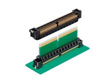
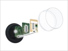
4. Sequential mating structure
Two sequential contacts in the signal male unit and one sequential contact in the power supply female unit are provided for safety operation.
5. Panel installation
Installation to a panel uses a single-action method on the anchored side and a floating screw structure on the floating side which permits smooth insertion and disconnection without forcing.
- Connector Type
- Contact
- Parts
- Panel Mounting Style
- Cable Assembly
- No
- Cable Length
- Generic Type
- Industry Standard
- Safety Standards
- Performance Characteristics
- Transmission Rate
- Water Resistance
- Salt Spray Test Duration (Corrosion Resistance)
- 48 hours h
- Mating/Unmating Cycles
- 3000
- Number of Positions
- Remarks on Number of Positions
- Contact Pitch
- Contact Plating
- Gold
- Locking Style
- Rated Current
- 12.0 A
- Rated Current other
- Rated Voltage (AC)
- AC 300.0 V
- Rated Voltage (AC) other
- Rated Voltage (DC)
- DC 300.0 V
- Rated Voltage (DC) other
- Mounting Style
- Connector Orientation
- Mounting Side
- Wire Termination Method
- Crimping
- Recommended Min. Wire Size (AWG)
- 18
- Recommended Max. Wire Size (AWG)
- 16
- Recommended Min. Wire Size (mm²)
- Recommended Max. Wire Size (mm²)
- Operating Temperature Max.
- 105 ℃
- Operating Temperature Min.
- -55 ℃
- Mounting direction
- Floating Range(XY)(mm)
- Effective Mating Length(Z)(mm)
- Cable Color
- Connector Type Details
List of Connectors (Specification Sheet, 2D drawings, 3D models, Distributor inventory)


Document
In cases where the application will demand a high level of reliability, such as automotive, please contact a company representative for further information.