-
Category
-
I/O Connectors
 List of useful search tools
-
Standard Products
List of useful search tools
-
Wire-to-Board
List of useful search tools
- Board-to-Board, Board-to-FPC
-
FPC/FFC Connectors
List of useful search tools
-
RF/Coaxial
List of useful search tools
-
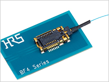
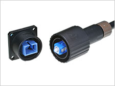
Fiber Optic Connectors
List of useful search tools
-
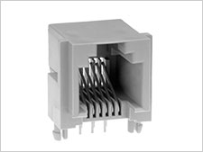
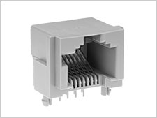
Modular Connectors / Ethernet Connectors
List of useful search tools
-
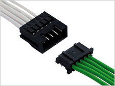
Wire-to-Wire
List of useful search tools
-
IC Card/IC Socket
List of useful search tools
-
Card Edge Connectors
List of useful search tools
-
Automotive Connectors
List of useful search tools
-
Power Connectors
List of useful search tools
-
High Speed Connectors
List of useful search tools
-
Sealed connector
List of useful search tools
-
I/O Connectors
-
Applications
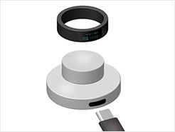
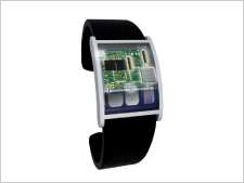
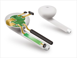
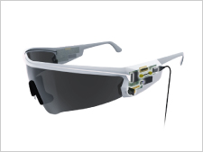
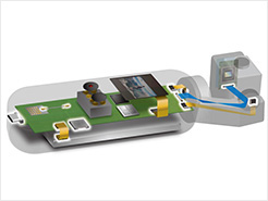
- Smartphone & Wearable
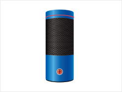
- Smart Appliances
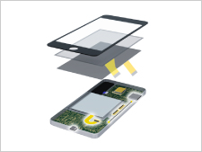
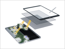
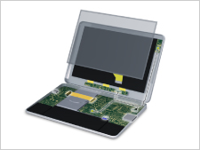
- PC & Tablet
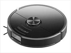
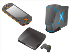
- Other Consumer Equipment
- Autonomous Car
- Powertrain (For Automotive)
- Infotainment (For Automotive)
- Connected Cars
- Automotive Lighting
- Smart Grid
- Industrial Automation
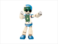
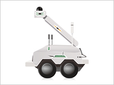
- Robots
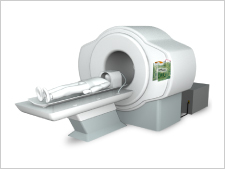
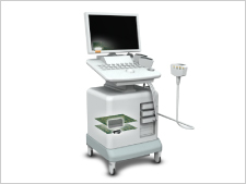
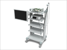
- Medical
- Telecommunications/Networking
- Data Centers
- Rail/Commercial Vehicles
- Other Industrial Equipment
- Office Automation
 Recently Reviewed Application
- -
-
Category
-
I/O Connectors
List of useful search tools
-
Standard Products
List of useful search tools
-
Wire-to-Board
List of useful search tools
-
Board-to-Board, Board-to-FPC
-
FPC/FFC Connectors
List of useful search tools
-
RF/Coaxial
List of useful search tools
-
Fiber Optic Connectors
List of useful search tools
-
Modular Connectors / Ethernet Connectors
List of useful search tools
-
Wire-to-Wire
List of useful search tools
-
IC Card/IC Socket
List of useful search tools
-
Card Edge Connectors
List of useful search tools
-
Automotive Connectors
List of useful search tools
-
Power Connectors
List of useful search tools
-
High Speed Connectors
List of useful search tools
-
Sealed connector
List of useful search tools
-
I/O Connectors
-
Applications
- Consumer
-
Smartphone & Wearable
Recently Reviewed Application
Recommended Applications
-
Smart Appliances
Recently Reviewed Application
Recommended Applications
-
PC & Tablet
Recently Reviewed Application
Recommended Applications
-
Other Consumer Equipment
Recently Reviewed Application
Recommended Applications
- Automotive
-
Autonomous Car
Recently Reviewed Application
Recommended Applications
-
Powertrain (For Automotive)
Recently Reviewed Application
Recommended Applications
-
Infotainment (For Automotive)
Recently Reviewed Application
Recommended Applications
-
Connected Cars
Recently Reviewed Application
Recommended Applications
-
Automotive Lighting
Recently Reviewed Application
Recommended Applications
- Industrial Machinery
-
Smart Grid
Recently Reviewed Application
Recommended Applications
-
Industrial Automation
Recently Reviewed Application
Recommended Applications
-
Robots
Recently Reviewed Application
Recommended Applications
-
Medical
Recently Reviewed Application
Recommended Applications
-
Telecommunications/Networking
Recently Reviewed Application
Recommended Applications
-
Data Centers
Recently Reviewed Application
Recommended Applications
-
Rail/Commercial Vehicles
Recently Reviewed Application
Recommended Applications
-
Other Industrial Equipment
Recently Reviewed Application
Recommended Applications
-
Office Automation
Recently Reviewed Application
Recommended Applications